INTRODUCTION:
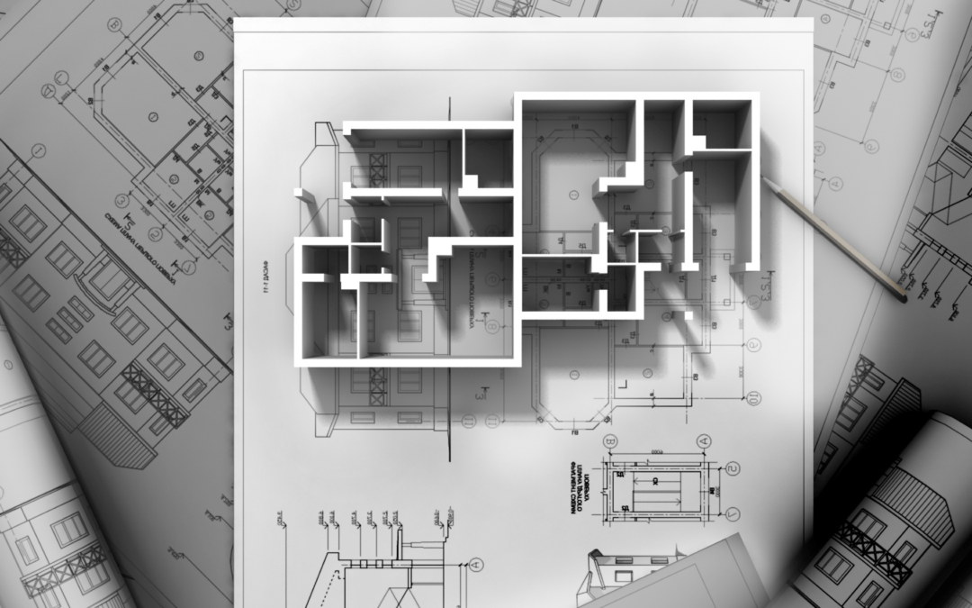
An engineer visualizes in his mind what plans to build. That idea is laid out on paper in a drawing format and forms the representation of what the builder plans to put up. This drawing is the marvel of putting up a building as one can actually how see things will be done in minute detail even before the first shovel of earth turned
If build something which is small scale then it’s built without the drawing also. For large projects drawings are necessary. In order to understand the size, shape color, and feel of the building that is being planned. If these comprehensive outlines are completed then the construction can start.
MEP system deals with the Mechanical Electrical, and Plumbing requirements of the structure. In the construction business, the standard school thought aims at making sure a building is not only aesthetically appealing But should also safe, energy-efficient, and structurally sound.
MEP shop drawings are created by combining the architectural, structural, and civil shop drawings for a project.
Different Types of MEP drawings:
1 . Penetration Drawing
2. MEP Shop Drawing Detailing
3. Block-out and Sleeve Drawing.
4. Pipe Spool Drawing
5. Coordination Drawing
6. As-built Drawing
1: Penetration drawing
- These drawings are designed for penetrants, i.e., for mechanical, electrical, plumbing, and structural items that pass through an opening in a wall or floor, such as electrical conduits, electrical cables, pipes, ducting, and cable trays.
- Sizing of all openings needs to be done with accuracy as they create a space between the surroundings and penetrants. Therefore, communication between the team members is very important to ensure proper sizing of the openings before these works are carried out
2: MEP Shop drawing
- This is done for dimensioning, elevation, and annotations. They are created before the initiation of the construction work of a project. These drawings offer an increased level of detail for fabrication and installation. Some components may require prefabrication including ductwork, air-handling units, and custom piping connections between equipment and building sites.
- The accuracy of the final dimensions is taken into consideration from shop drawings instead of the design details and layout drawings. Shop drawings are very important for the exemplification of the true image of a construction project.
- The design needs to be approved by the construction team and after getting the consent, the shop drawings help in determining how the construction process is carried out. Shop drawings can be used to detect any inconsistency before field installation.
3: Block-out and Sleeve Drawing
- These drawings are useful for cement and steel contractors. The drawings are of great help when it is concerned with where to leave space on the floor and ceiling cutouts.
- Sleeve drawings are used to make sure that the holes left between the floors and the walls are properly placed for piping and ductwork.
4: Pipe Spool Drawing
- A spool is an assembly of pipes and is concerned with the components that can be pre-fabricated in the workshop for installation and shipped to the site afterward for assembling. These drawings act as a guide to the plumbers to figure out what needs to be done.
- The spools are connected at different junctions throughout any concerned structure. The drawings are optimized to convey all the information that is essential for the fabricators to manufacture and assemble the spool accurately.
- Spool drawing is obtained after collecting the complete information of all parts welded together into a single drawing
5: Coordination Drawing
- Coordination is very important for the success of any building project. It simply means avoiding physical conflicts in the layout of the equipment and the routing of ducts, electrical piping, and drainage pipes through the building. When any building project has intense MEP requirements, the risk of interference problems is high.
- Elimination of coordination problems is a prerequisite for starting the construction work for projects with an intense MEP system.
- Coordination drawings are necessary to begin the construction work and eliminate any physical conflicts.
6: As-built Drawing
- As-Built Drawings are made after the construction of the building has been finished. They are used to depict on paper how the building has been constructed. As a matter of fact, as-built drawings are used to make a comparison between what was the planned construction and how the construction has been made in the end.
- As-built drawings are used to determine the difference between the pre-development and post-development of a building.
- They are issued to the clients after the project works are wound up. They include everything from the structure to the installation and their details. They are important from the perspective of the client and allow them to survey the product.

